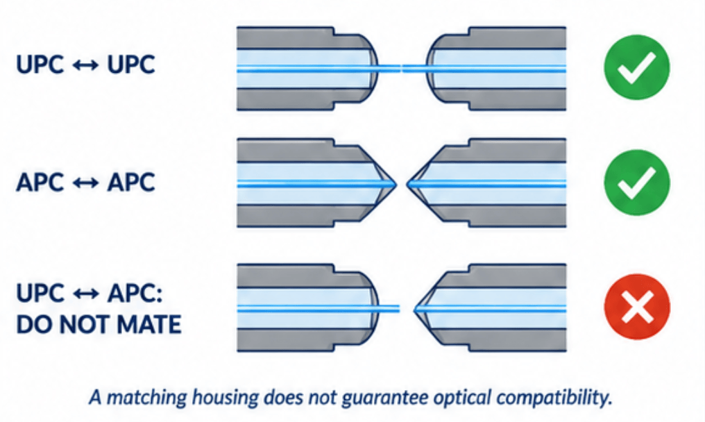
Identify a fiber connector by its mechanical interface and end-face polish—not by color alone. “LC” and “SC” describe connector families; “UPC” and “APC” describe how the fiber end face is polished. Both details matter when selecting a patch cord or checking a connection. A plug that fits an adapter is not necessarily optically compatible with the connector behind it. In particular, never directly mate UPC and APC end faces: the mismatch can cause high loss, strong reflections, and end-face damage.
For purchasing and field identification, record the connector family, polish, fiber specification, and configuration at each end. For multifiber interfaces, also establish the pin arrangement, fiber layout, and polarity before selecting a replacement.
Identify the Connector Family First
Look at the housing, locking mechanism, and ferrule arrangement. The ferrule is the precision component that holds and aligns the fiber at the mating interface.
| Connector family | Practical identification cues | Ferrule arrangement | What to confirm before connecting |
|---|---|---|---|
| LC | Small rectangular housing with a latch; two plugs may be held together as a duplex pair | One fiber per 1.25 mm ferrule | LC interface, polish, fiber specification, and duplex orientation where applicable |
| SC | Larger rectangular push-pull housing | One fiber per 2.5 mm ferrule | SC interface, polish, and simplex or duplex configuration |
| ST | Round body with a bayonet-style twist lock | One fiber per 2.5 mm ferrule | ST-compatible interface, fiber specification, and specified polish |
| FC | Round body with a threaded coupling nut | One fiber per 2.5 mm ferrule | FC interface, polish, and the manufacturer’s keying requirements |
| MPO | Rectangular multifiber interface with a keyed housing; the ferrule contains an array of fiber positions | Multiple fibers in one ferrule, with guide-pin alignment | Exact interface variant, fiber layout, populated positions, polish, pins, key orientation, and polarity |
The ferrule sizes shown for LC, SC, and ST are documented in Corning’s UniCam connector specifications. Fluke Networks’ cleaning-tool documentation also groups FC with the 2.5 mm interfaces. Its multifiber testing documentation describes MPO ferrules, keys, and pinned-to-unpinned mating. Ferrule diameter helps identify suitable inspection and cleaning tools; it does not make different connector families interchangeable.
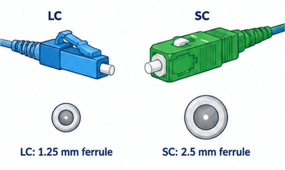
Housing identification is only the first step. Corning’s single-mode connector catalog, for example, lists both LC and SC products with different polish options. Specifying “an SC connector” therefore leaves a decision-critical detail unresolved.
UPC vs APC: The Difference Is at the End Face
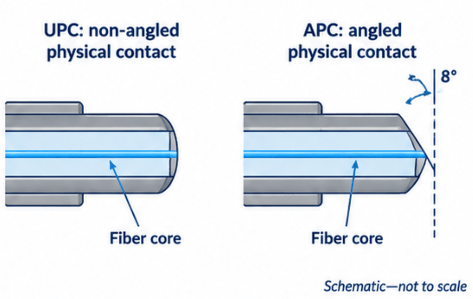
UPC means ultra physical contact. APC means angled physical contact. Both are physical-contact interfaces when correctly paired, but their end-face geometries differ. Fluke Networks describes UPC as slightly rounded and conventional APC as having an 8-degree angle. UPC should not be interpreted as a perfectly flat, air-gap interface.
| Attribute | UPC | APC |
|---|---|---|
| End-face geometry | Curved physical-contact surface without the APC angle | Angled physical-contact surface; conventional interfaces use an 8-degree angle |
| Reflected-light behavior | More reflected light can couple back toward the source through the core | The angle directs reflected light away from the core, reducing back-reflection |
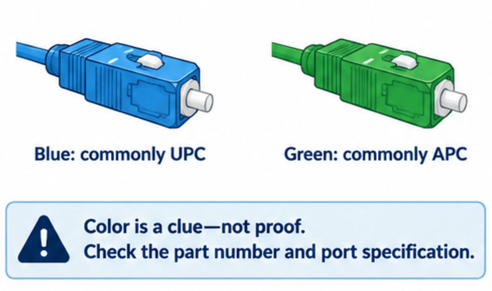
| Common single-mode identification convention | Blue housing, boot, or adapter | Green housing, boot, or adapter |
| Direct mating requirement | Matching UPC interface | Matching APC interface |
| Selection basis | Equipment-port requirements and specified optical performance | Equipment-port requirements and specified optical performance, particularly where reflections matter |
These distinctions explain why APC appears in PON and other reflection-sensitive systems. They do not make APC a universal replacement for UPC: the installed equipment interface still determines what may be connected.
PC, SPC, and UPC Labels Are Not Equivalent Performance Specifications
PC means physical contact. Manufacturer catalogs may also identify SPC, or super physical contact, alongside UPC. Do not replace a specified polish grade with the generic description “PC” unless the supplier confirms the required performance.
A useful example appears in Corning’s UniCam single-mode family specification, revision January 6, 2015, page 2. Its listed SPC and UPC versions have the same typical and maximum insertion-loss figures, but different reflectance limits:
| Listed UniCam single-mode polish | Typical insertion loss | Maximum insertion loss | Reflectance |
|---|---|---|---|
| SPC | 0.2 dB | 0.5 dB | ≤ −40 dB |
| UPC | 0.2 dB | 0.5 dB | ≤ −55 dB |
The document identifies the insertion-loss figures as applying per connector pair. These are specifications for that product family and revision—not universal limits for every SPC or UPC connector. They demonstrate why polish and reflection performance must be checked separately from insertion loss.
Treat Connector Colors as Identification Clues
For conventional single-mode patching, blue commonly identifies non-APC physical-contact connectors, often UPC, while green identifies APC. The Fiber Optic Association also documents beige for 62.5/125 µm multimode, black for 50/125 µm OM2, aqua for OM3/OM4, and lime for OM5 connector bodies or associated components.
Color is useful for sorting likely candidates, but it is not a complete part specification:
- A blue housing does not prove a particular UPC reflectance rating. Corning’s cited catalog uses blue LC and SC housings for both SPC and UPC, with different boot colors.
- Metal-bodied connectors may use boot color rather than housing color for identification.
- A cable jacket and its connector housing convey different information. A yellow jacket may identify single-mode cable, while the connector color distinguishes the termination.
- Project conventions and manufacturer implementations can differ. Resolve uncertainty through the cable marking, part number, port documentation, or assembly drawing.
Do not infer polish from an ordinary visual examination of the exposed ferrule. Use product identification to establish the specified geometry, and a suitable inspection system to assess end-face condition. APC inspection may require a dedicated probe tip to obtain a properly focused view.
Check Compatibility at Every Mating Interface
A mating decision concerns the two end faces that actually meet. It is not determined by the names of the two devices at opposite ends of a cable.
| Proposed connection | Decision | Required action |
|---|---|---|
| LC/UPC to LC/UPC through an appropriate LC adapter | Compatible in connector family and polish | Confirm fiber specification, configuration, cleanliness, and required performance |
| SC/APC to SC/APC through an appropriate SC/APC adapter | Compatible in connector family and polish | Confirm the specified interface and inspect both end faces |
| SC/UPC to SC/APC through an SC adapter | Do not mate | Replace the incorrect termination or use a correctly specified transition patch cord |
| LC plug directly into an SC adapter | Mechanically incompatible | Use an appropriate LC-to-SC patch cord or a documented compatible hybrid adapter arrangement |
| Pinned MPO to unpinned MPO | Correct pin relationship, but not sufficient by itself | Check interface variant, polish, fiber layout, key orientation, and polarity |
| Pinned MPO to pinned MPO, or unpinned MPO to unpinned MPO | Incorrect conventional MPO pairing | Obtain the specified mating arrangement; do not force the connection |
The UPC/APC prohibition applies even when the housings fit the same adapter. Conventional MPO mating requires one pinned connector and one unpinned connector; that mechanical relationship does not establish the correct optical lane mapping.
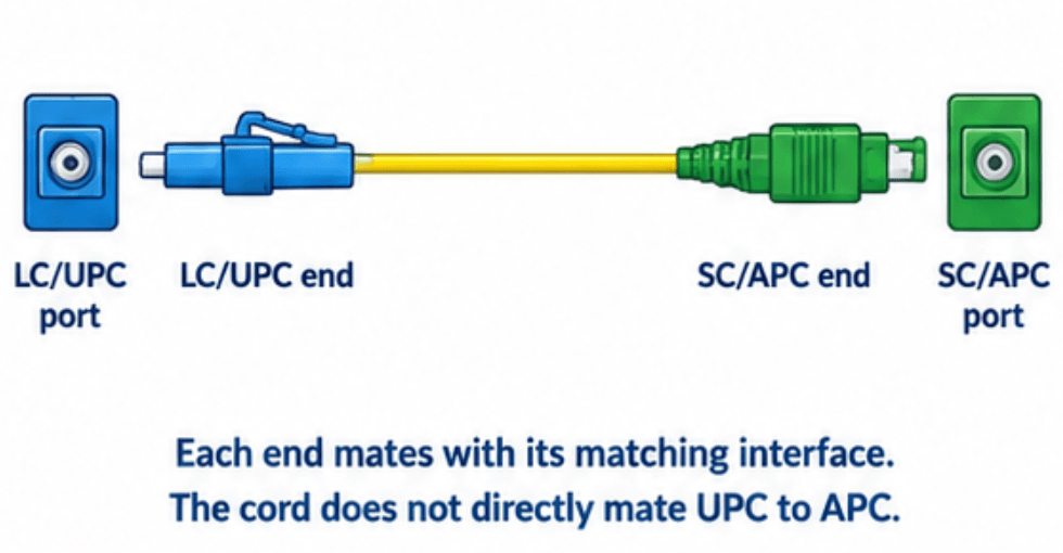
A Transition Patch Cord Does Not Directly Mate UPC to APC
An LC/UPC-to-SC/APC patch cord can connect two differently specified interfaces without placing a UPC face against an APC face:
- Its LC/UPC end mates with the matching LC/UPC interface.
- Its SC/APC end mates with the matching SC/APC interface.
- The continuous fiber inside the cord links the two ends.
The connector families and polish types differ between the ends of the assembly, not across either mating pair. Fluke Networks uses hybrid UPC-to-APC cords in its documented APC testing arrangements for this reason. An adapter alone does not change either connector’s polish.
That arrangement establishes a possible physical connection—not compatibility between the connected systems. The equipment and cable specifications must still agree on the required fiber and optical application.
MPO Requires More Than a Fiber Count
For an MPO replacement, “12-fiber” or “16-fiber” is not a complete ordering description. Check:
- The exact connector and ferrule variant.
- The number and arrangement of fiber positions, including which positions are populated.
- Whether each end is pinned or unpinned.
- The specified polish at each mating interface.
- Key orientation and the complete end-to-end fiber mapping.
Polarity must route each transmitting lane to its intended receiving lane. A correctly seated connector can still produce a nonfunctional channel if that mapping is wrong. Use the equipment interface specification and assembly drawing rather than assuming that matching housing appearance or fiber count establishes compatibility.
Read Optical Specifications Without Mixing Metrics
Insertion loss and reflected power describe different effects. A connector’s polish label does not establish either its installed loss or its installed reflection performance.
| Metric | What it describes | Preferred direction |
|---|---|---|
| Insertion loss | Optical power lost through the specified connection or assembly | Lower dB value |
| Return loss | Incident power relative to reflected power, expressed logarithmically | Higher positive dB value |
| Reflectance | Reflected power relative to incident power, expressed logarithmically | More negative dB value |
Return loss and reflectance have opposite signs when they describe the same reflected-power ratio under the same measurement conditions. A connection specified at reflectance ≤ −55 dB therefore corresponds to return loss ≥ 55 dB for that same boundary. Do not compare a single-connection reflectance rating with whole-link optical return loss as though they describe the same measurement.
For procurement, require the supplier to identify:
- Whether the loss specification applies to a mated pair, a complete patch cord, or another stated measurement boundary.
- Whether the value is typical or a guaranteed maximum.
- The test wavelength, fiber specification, mating conditions, and test method.
- The reflection requirement and whether it is expressed as reflectance or return loss.
Corning’s UniCam example illustrates the importance of these distinctions: its typical insertion loss is not its maximum, and its UPC reflectance figure is not an APC rating. Do not transfer a value from one row or product family to another.
For preliminary link-loss estimates, count a specified mated-pair allowance once for each connection. Do not assign that full allowance independently to both plugs in the same pair. The resulting estimate remains a planning allowance; it is not a measurement of the installed connection.
Record These Fields Before Ordering
Write the two ends separately. A purchasing line that says only “single-mode fiber patch cord” or “green SC cable” leaves too much unresolved.
| Specification field | What to record |
|---|---|
| End A interface | Connector family, polish, and equipment or panel port identification |
| End B interface | Connector family, polish, and equipment or panel port identification |
| Fiber specification | Required single-mode or multimode designation and relevant manufacturer specification |
| Assembly configuration | Simplex, duplex, multifiber trunk, or breakout |
| Polarity | Duplex orientation or complete multifiber mapping required by the channel |
| Multifiber details | Interface variant, fiber positions, populated positions, pins, and keying at each end |
| Optical performance | Maximum insertion loss and required reflectance or return loss, with test conditions |
| Physical construction | Length, cable diameter, boot style, routing constraints, and required cable rating |
| Product traceability | Manufacturer, exact part number, drawing or datasheet revision, and supplied test record |
For example, a conditional purchase description could read:
“Single-mode simplex patch cord, SC/APC at End A and LC/UPC at End B, length and cable construction per the installation drawing, with maximum assembly loss and reflection performance stated at the required test wavelengths.”
That description is appropriate only after documentation confirms SC/APC at one interface and LC/UPC at the other. It does not establish that the devices themselves support the same service.
Inspect Before Mating, Then Test the Installed Connection
Before handling an exposed interface, follow the site’s optical safety procedure and establish whether the fiber is active using appropriate equipment. Never look directly into a fiber or port; the transmitted light may be invisible and can injure the eyes.
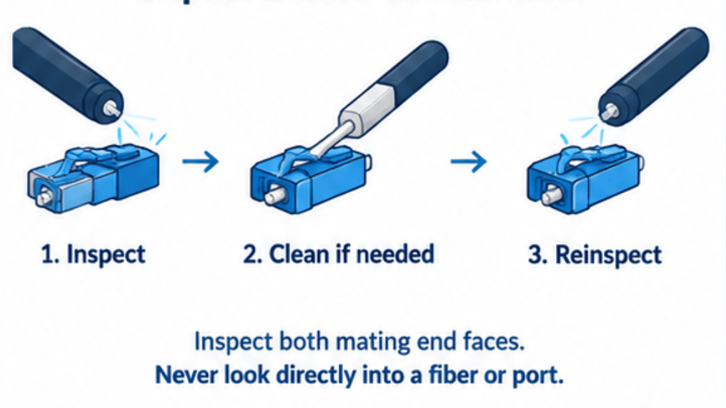
Use the following connection sequence:
- Confirm the port identity and specified connector interface. Resolve unknown polish or multifiber pinning before inserting anything.
- Inspect both mating end faces using a probe and tip suitable for the connector geometry.
- If contamination is present, clean with a connector-compatible fiber-cleaning tool or approved method.
- Reinspect after cleaning. A cleaning action is not evidence that contamination has been removed.
- Connect only after the interfaces are correctly identified and meet the applicable end-face acceptance requirements.
New patch cords and dust-capped connectors still require inspection. Caps protect against handling damage but do not guarantee clean end faces. Contamination can also transfer from one side of a connection to the other.
Use the test instrument’s own instructions when selecting reference cords and adapters. Some optical power-meter inputs use noncontact arrangements that can accept interfaces a physical-contact source or OTDR port cannot. Such model-specific allowances do not permit direct APC-to-UPC mating elsewhere in the test setup.
Finally, distinguish identification, inspection, and optical testing. Correct housing and polish identification establish whether components are candidates for connection. Inspection assesses visible end-face condition. Loss and reflection testing assess optical performance under the documented test conditions. None can substitute for the others when accepting an installed connection.